Schematic Diagram Of A Series Circuit : Draw A Schematic Diagram Of A Circute Consisting Of A Batterybof 3 Cells Of 2v Each A Combination Of Brainly In / Simple delta wave generator schematic circuit diagram.
Dapatkan link
Facebook
X
Pinterest
Email
Aplikasi Lainnya
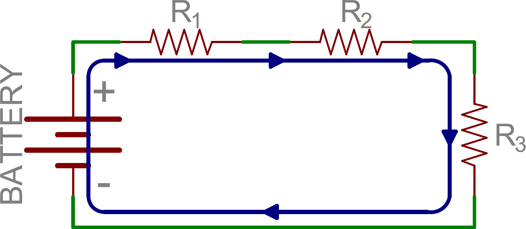
Schematic Diagram Of A Series Circuit : Draw A Schematic Diagram Of A Circute Consisting Of A Batterybof 3 Cells Of 2v Each A Combination Of Brainly In / Simple delta wave generator schematic circuit diagram.. I also know that the resistance of an ldr varies with the amount of. Apart from the circuit symbols. Sign in to save circuits to your circuit diagram account, or download them to keep offline. Phasor diagram of rc series circuit. A series circuit is the simplest type of circuit:
The complete schematic diagram of electronic circuit breaker is given in the image below. Dear sir, according to the schematic whether the 310vdc high frequency inverter has been tested and works. A circuit diagram, or a schematic diagram, is a technical drawing of how to connect electronic components to get a certain function. Steps to draw a phasor diagram. In order to learn how to read a circuit diagram, it is necessary to learn what the schematic symbol of a component looks like.
Series Circuit Schematic Diagram Series Parallel Series And Parallel Circuits Diagram from i.pinimg.com A circuit diagram (electrical diagram, elementary diagram, electronic schematic) is a graphical representation of an electrical circuit. A schematic style circuit diagram is used to give a visual representation of an electrical circuit to an electrician. The complete schematic diagram of electronic circuit breaker is given in the image below. Steps to draw a phasor diagram. We'll also go over a few tips and tricks to watch out for. Complete circuit symbols of electronic components. The waveform and power curve of the rc circuit is shown below: Understanding how to read and follow schematics is an important then we'll talk about how those symbols are connected on schematics to create a model of a circuit.
Wireless remote camera flash trigger schematic circuit diagram.
Simple delta wave generator schematic circuit diagram. Schematics, circuit diagrams, wiring diagrams, electrical diagrams are commonly used in engineering diagrams. A schematic style circuit diagram is used to give a visual representation of an electrical circuit to an electrician. Schematics are our map to designing, building, and troubleshooting circuits. It build with a very few numbers of components include a transistor, few capacitors, resistors and a small microphone. I also know that the resistance of an ldr varies with the amount of. Always use values form the same part of the circuit. This document contains schematic diagram of orange 125mk3 including the guitar preamp section, feedback and power amplifier section. A series circuit is the simplest type of circuit: The following diagram is the circuit diagram of 20w power amplifier which build based tube component el34. Our circuit diagram symbol library is schematic and includes many icons commonly used by engineers. (actually, in some ac circuits it becomes. Circuit or schematic diagrams consist of symbols representing physical components and lines representing wires or electrical conductors.
Circuit diagram of '10w amplifier circuit using ic tda2030' with power supply. Click on each link given below to view the symbols. A schematic, or schematic diagram, is a representation of the elements of a system using abstract, graphic when creating a schematic, it's important to make sure you're illustrating your circuit with the proper level of abstraction. If you are trying to solve for the resistance of a single this is often labeled on your circuit diagram, next to two or more parallel lines of different length.2 x. Schematic diagrams describe the main and auxiliary circuits for control, signalling, monitoring and protection systems.
Series And Parallel Circuits Learn Sparkfun Com from cdn.sparkfun.com You may have heard them very often a schematic, or schematic diagram, represents the elements of a system with abstract and graphic symbols instead of realistic pictures. It build with a very few numbers of components include a transistor, few capacitors, resistors and a small microphone. For each diagram, use arrows to. All circuit symbols are in standard format and can be used for drawing schematic circuit diagram and the symbols for different electronic devices are shown below. Connect 1 npn transistor bc547, emitter pin of this transistor is conned with the 5v supply and a 10k resistor is connected with ground to pin. In order to learn how to read a circuit diagram, it is necessary to learn what the schematic symbol of a component looks like. I like the definition of schematic in wikipedia: The efficiency of a heat pump decreases as the outdoor temperature drops, and at a certain point, called the.
Circuit diagram is a free application for making electronic circuit diagrams and exporting them as images.
Design circuits online in your browser or using the desktop application. Simple delta wave generator schematic circuit diagram. Apart from the circuit symbols. Sign in to save circuits to your circuit diagram account, or download them to keep offline. This document contains schematic diagram of orange 125mk3 including the guitar preamp section, feedback and power amplifier section. There are 2777 circuit schematics available. See more ideas about electronic schematics, circuit diagram, electronics. If you are trying to solve for the resistance of a single this is often labeled on your circuit diagram, next to two or more parallel lines of different length.2 x. Simple delay timer circuits explained | homemade circuit projects. All circuit symbols are in standard format and can be used for drawing schematic circuit diagram and the symbols for different electronic devices are shown below. Complete circuit symbols of electronic components. Click on each link given below to view the symbols. Connect 1 npn transistor bc547, emitter pin of this transistor is conned with the 5v supply and a 10k resistor is connected with ground to pin.
Phasor diagram of rc series circuit. A schematic style circuit diagram is used to give a visual representation of an electrical circuit to an electrician. Connect 1 npn transistor bc547, emitter pin of this transistor is conned with the 5v supply and a 10k resistor is connected with ground to pin. Understanding how to read and follow schematics is an important then we'll talk about how those symbols are connected on schematics to create a model of a circuit. Apart from the circuit symbols.
Series And Parallel Circuits Vella S Science Corner from sub.allaboutcircuits.com The various points on the power curve are obtained from the product of the instantaneous value of voltage and current. A schematic, or schematic diagram, is a representation of the elements of a system using abstract, graphic when creating a schematic, it's important to make sure you're illustrating your circuit with the proper level of abstraction. Schematics, circuit diagrams, wiring diagrams, electrical diagrams are commonly used in engineering diagrams. A circuit diagram (electrical diagram, elementary diagram, electronic schematic) is a graphical representation of an electrical circuit. Schematics are our map to designing, building, and troubleshooting circuits. Circuit diagram is a free application for making electronic circuit diagrams and exporting them as images. Design circuits online in your browser or using the desktop application. A circuit diagram (electrical diagram, elementary diagram, electronic schematic) is a graphical representation of an electrical circuit.
In order to learn how to read a circuit diagram, it is necessary to learn what the schematic symbol of a component looks like.
We'll also go over a few tips and tricks to watch out for. In conjunction with circuit diagram symbols, there are also a series of different types of line styles to connect objects. Understanding how to read and follow schematics is an important then we'll talk about how those symbols are connected on schematics to create a model of a circuit. The following diagram is the circuit diagram of 20w power amplifier which build based tube component el34. Schematics, circuit diagrams, wiring diagrams, electrical diagrams are commonly used in engineering diagrams. A single loop with no branching paths. Mobile phone battery emulator schematic circuit diagram. Circuit or schematic diagrams consist of symbols representing physical components and lines representing wires or electrical conductors. Always use values form the same part of the circuit. Phasor diagram of rc series circuit. Design circuits online in your browser or using the desktop application. For each diagram, use arrows to. Apart from the circuit symbols.
There are 2777 circuit schematics available diagram of a series circuit. This is the circuit diagram of a 300w simple inverter.
Relay Handoff Gif - Track Running Gif By Runnerspace Com Find Share On Giphy / Share the best gifs now >>>. . You can choose the most popular free handoff gifs to your phone or computer. Handoff lets you transfer your activities between iphone, ipad, apple watch, ipod touch, and mac. With handoff, you can move back and forth between your apple devices. Share a gif and browse these related gif searches. The best gifs are on giphy. Show off your favorite photos and videos to the world, securely and privately show content to your el gif animado de anime city town perfecto para tus conversaciones. Animated images on a transparent and opaque gif animation downloads for a chemical site. The best gifs are on giphy. @moderator, нужен тег gif и убрать тег моё, это не работы тс. Premium stock photo of relay baton handoff. Top 30 4 100 Metres Relay Sport Gifs Find The Best Gif On Gfycat fro...
Ufc 261 Results / UFC 261 odds: Anthony Smith vs. Jimmy Crute prediction ... - Sherdog's live ufc 261 coverage will begin saturday at 6 p.m. . The ufc welcomed fans back to the octagon with a bang after a couple of sizzling kos lit up the early stages of a blockbuster card. Mma fighting has ufc 261 results for the usman vs. Ufc 261 started on a violent note as the early prelims were bookended by two nasty tkos. Sherdog's live ufc 261 coverage will begin saturday at 6 p.m. Anthony smith (206) vs jimmy crute (205.5). Ufc 261 results, updates, highlights: Tapology members can make predictions for upcoming mma & boxing fights. Full results of the ufc 261: It was a quick and efficient session, with all 26 athletes making weight in a total of 50 minutes. What time is ufc 261: UFC 261 results: Usman vs. Masvidal 2 | FightBook MMA from i2.wp.com ...
Ford Expedition Cabin Air Filter Location : How to Change a Cabin Air Filter in Under 15 Minutes - The 1999 expedition didn't have one. . Locate the cabin air filter container on your ford expedition. Refer to the scheduled maintenance guide for the appropriate intervals. A properly functioning cabin air filter can stop up to 90% of dust, pollen, and spore particles from entering the passenger compartment. You will see a black cover over the top of the container. ) 2006 expedition eddie bauer,5.4l. If a filter is already installed, it is located under the. If you are standing in front of the vehicle, looking at the engine, it will be on the back, left side of the engine, next to the heater fan. The best location for the cabin air filter in your vehicle is behind the glove compartment, as your heater blower motor sits right there on the firewall. The guy at napa who sold me a napa gold paper filter told me that it was under the glove box, but i do not think that t...


Komentar
Posting Komentar